Are you getting the accuracy you expect in Pix4Dmapper?
Accuracy is also the major concern for people who work in surveying and geospatial industries.
This article will share some useful information regarding questions you may have: What overlap settings should I go with in order to get a better result? How do I know what the accuracy of my mapping outputs are? How can I improve the accuracy of my projects?
How does overlap affect accuracy?
But, first: What is accuracy in an aerial mapping project?
To explore how overlap affects accuracy, we compared the results generated from datasets with different image overlaps.
To ensure the results were as consistent as possible, we took one dataset as a control and altered the image overlap. Creating different overlap projects by taking images out allows us to keep most factors consistent and obtain a reliable result.
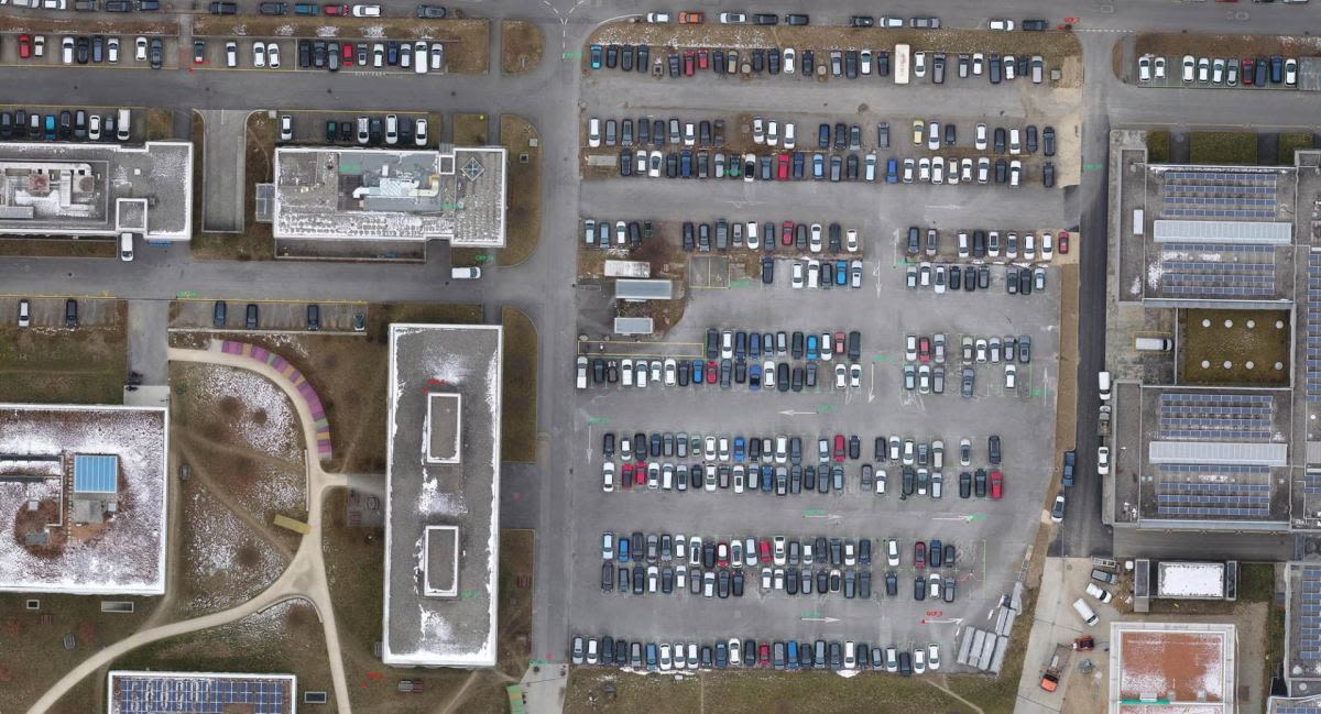
The original dataset was acquired by our Phantom 4 Pro with Pix4Dcapture. 21 points were surveyed using RTK method with a Triumph-LS. Five of them were used as ground control points (GCPs), and the rest were used as check points for examining the results from Pix4Dmapper. Adjacent images have 95% frontlap and 90% sidelap. All datasets have a ground sampling distance (GSD) of around 2.9 cm.
In order to know if the image overlap has an impact on accuracy, we compare the following three projects (which we will call Skip 0, Skip 3, and Skip 5):
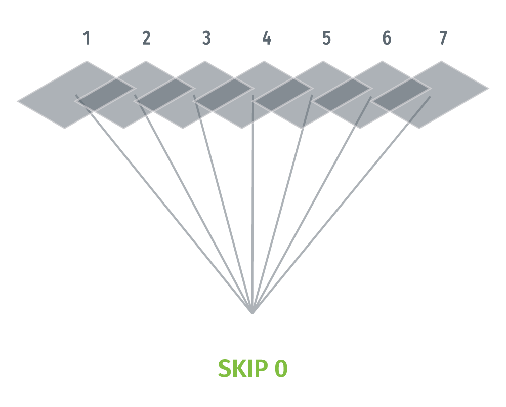
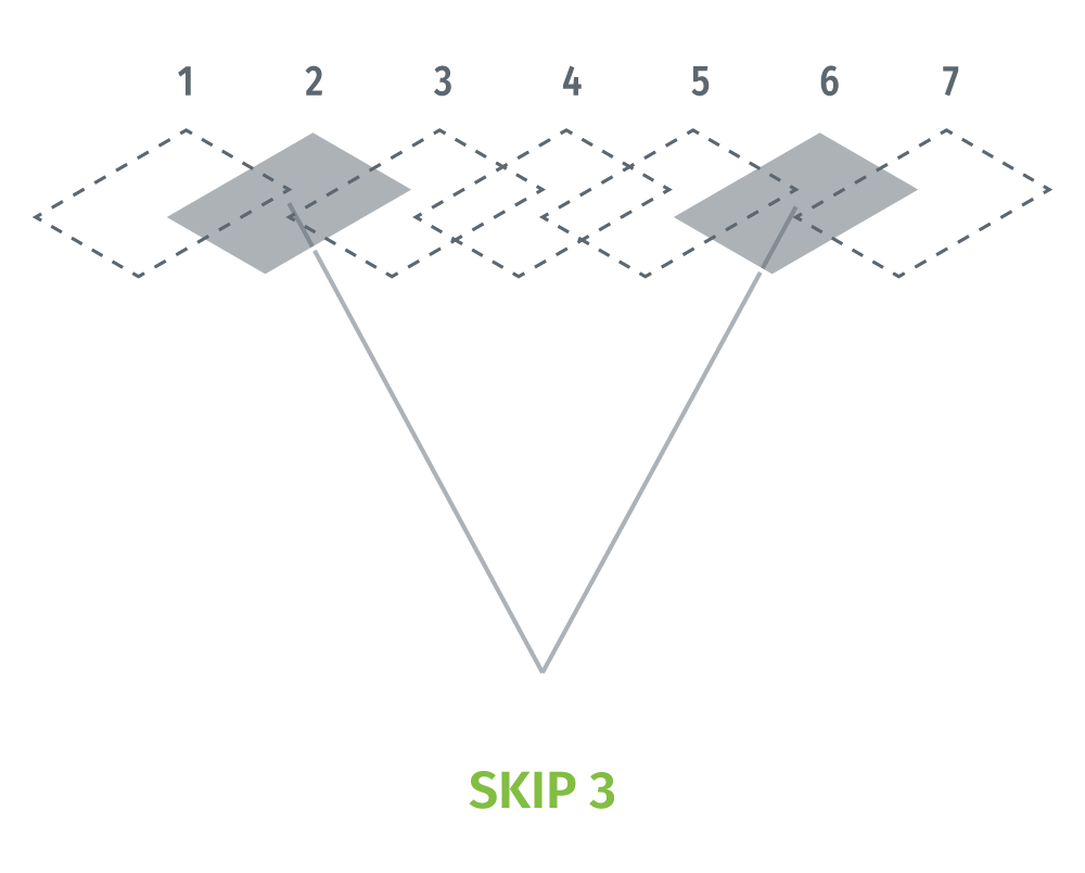
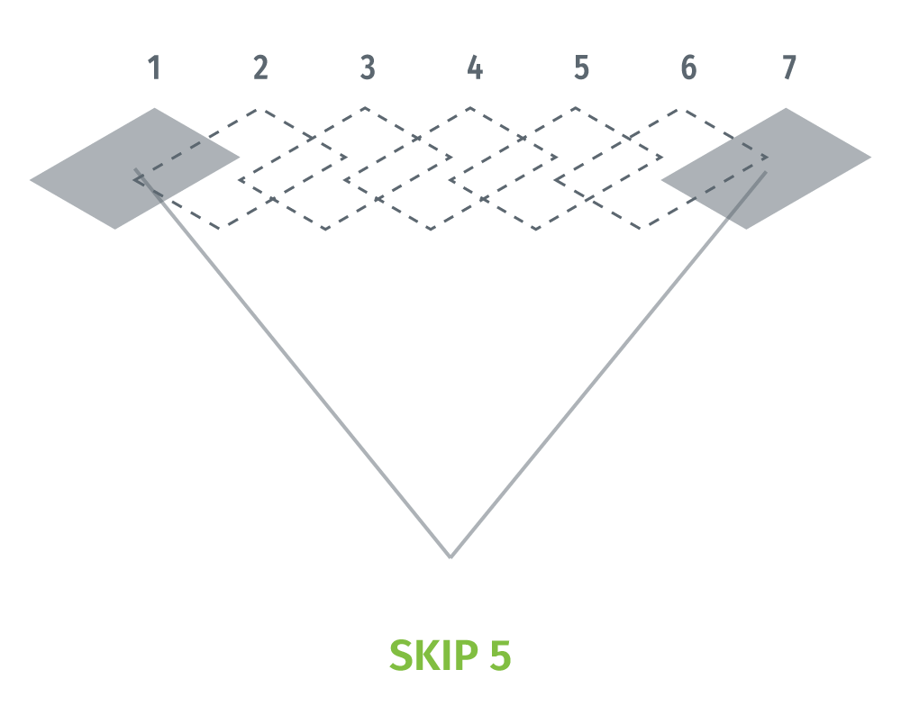
*Skip 0* is the project using the original dataset, *Skip 3* is the project created with one image selected out of four, and *Skip 5* was created with one image selected out of six.
In other words, the three datasets will have approximately 95%, 80%, and 73.5% of image overlap, respectively.
We'll talk more about the results later. For now, let's move on to...
Baseline and height flight ratio
In traditional photogrammetry theory, the vertical accuracy is relative to base-height ratio: the ratio of baseline and flying height. The term baseline refers to the distance between two camera positions.
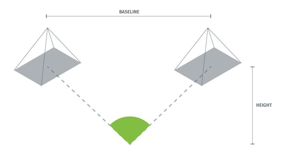
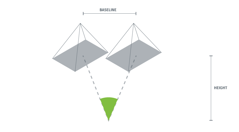
For the same flying height, shorter baseline (or more overlap) pairs intersect a 3D point at a more acute angle. A more acute angle will give you bigger errors in the vertical direction: one pixel of horizontal error will induce a vertical error of tan(90°-X/2) pixels, where X is the intersection angle in degrees.
The following diagram compares wide and short baselines. The intersection angle is marked in green.
However, more image overlap will give the software more information for the transition.
For example, matches not able to be found from a 60%-overlap image pair are probably going to be detected with more images taken between the pair.
So wide-baseline pairs give you better accuracy but short-baseline pairs increase the possibility of finding more matches.
Now the question is, is Pix4Dmapper powerful enough to find as many valid matches as possible, while taking into consideration that the matches were generated from different base-height ratios to ensure the best possible vertical accuracy? To answer this question, we proposed a standard workflow for quality assessment.
Standard workflow for quality assessment
In order to achieve the maximum quality assessment, we have prepared these 5 tips on how to increase the accuracy of your drone mapping projects, and the following workflow:
1. Import images and the GCPs, making sure they are marked on the wide-baseline pairs
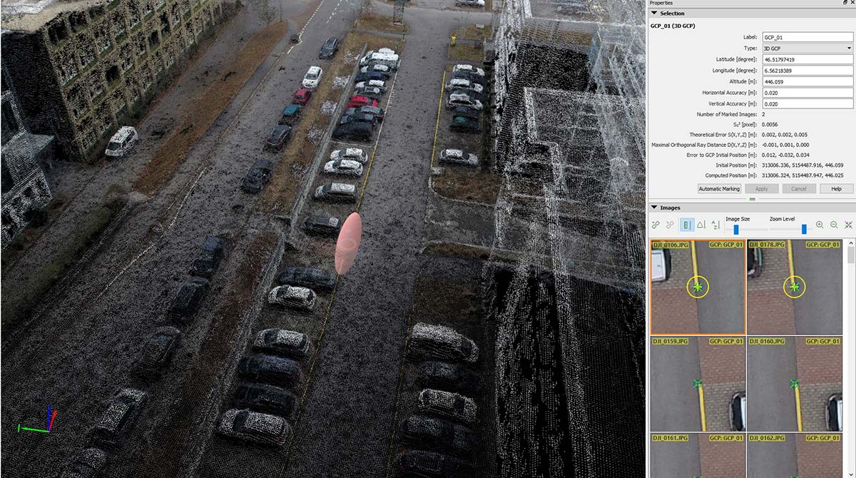
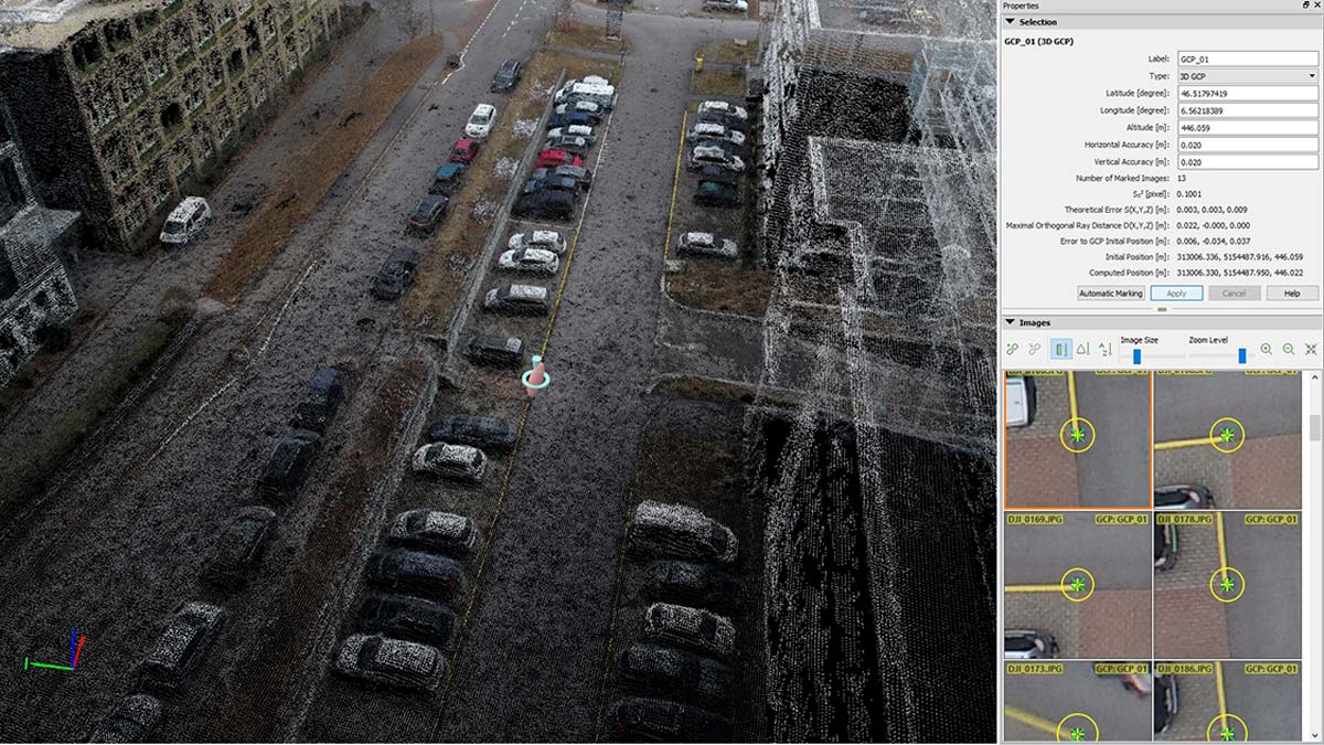
To know if your marks included the wide-baseline pairs. Check the error ellipsoid!
In Pix4Dmapper rayCloud, you may activate the display of *error ellipsoid* (marked in pink on the screenshots below), which shows you the error proportions in X, Y, Z directions. The ideal situation is a sphere, when the errors in three directions are equal. If not, the long radius points to the direction where a larger error is introduced. For example, a well-overlapped, nadir image dataset will have the long radius pointing to the Z direction. However, if the errors in Z direction exceed 5 times those of X and Y directions, where none of your input data has gross errors, there might be a problem caused by short baseline matches.Error ellipsoid showing if the marks also include wide-baseline pairs.
2. Import the check points, making sure they are marked on the wide-baseline pairs
To assess the calibration (bundle adjustment) result, ground-surveyed check points are imported. These check points also need to be correctly marked in order to tell the software where they are.
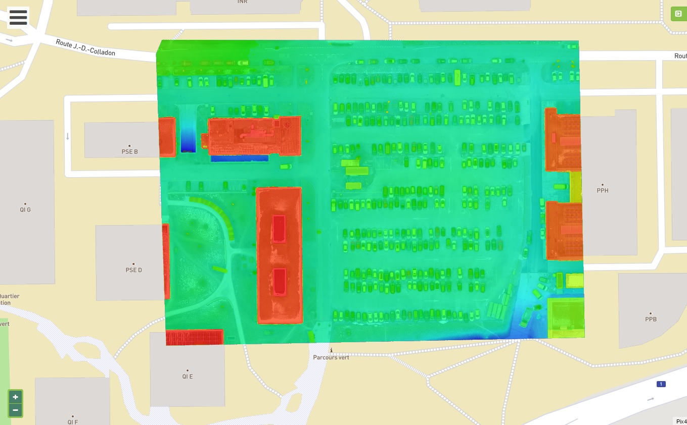
Check points are not taken into account for their 3D locations as the GCPs, but they would be triangulated as manual tie points. The quality of the digital surface model (DSM), processed using only the GCPs was examined by comparing the height difference from the check points.
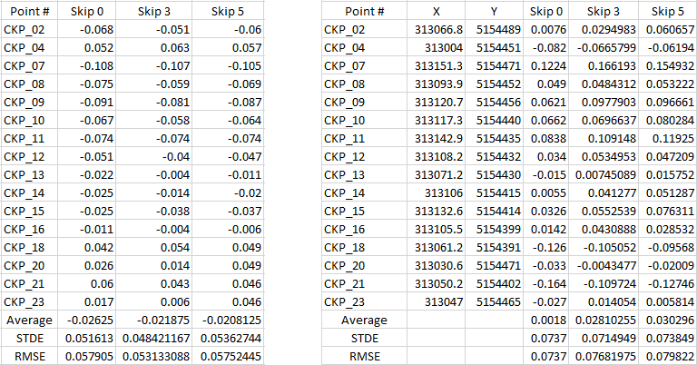
For users who need an accurate map: you may assess the orthomosaic by checking the horizontal shifts of the check points. In this dataset, the shifts are all less than one pixel.
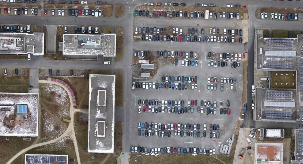
Conclusion: more overlap means more accuracy
Among the three different overlap projects, the highest overlap one Skip 0 gives the best results - however, all projects give less than one pixel of horizontal accuracy and less than three pixels of vertical accuracy.
Pix4Dmapper is capable of getting more contributions from wide-baseline matches, and higher overlap will ensure a better accuracy in your mapping output. To generate an accurate DSM and orthomosaic, you should capture nadir images with high degrees of image overlap, and remember to include wide-baseline pairs in both your GCP and check point marks. If you are not sure, always activate the error ellipsoid!Although higher image overlap gives you better results in Pix4Dmapper, the processing time is also nearly proportional to the number of images. The project Skip 0 took two hours to finish the initial processing, while Skip 3 and Skip 5 only took 20 and 10 minutes for a similar level of accuracy. Take these factors into consideration to make sure you benefit the most from the software!
